ROSTRA SEAT HEATER SUGGESTIONS
as reported by Chris Wilson
Please consult your local service manager before installing your
heaters for warnings and suggestions to avoid system damage and personal
injury. Follow the seat heater manufacturer instructions when in
conflict with the following suggestions, especially where safety is involved.
This procedure is only a suggested way to install the heaters. WARNING:
The air bags in the seat can cause serious personal injury and be expensive
to replace if accidentally energized!
1. Unhook the battery for safety due to the airbags in the seats!
I allowed 1 hour for the system to go dead before unclipping the two power
connectors under each seat. (Picture #1 shows the factory plugs after
seat removal.)
 #1 #1
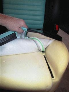
2. I installed the passenger seat heater under the smooth thigh area,
as hog rings tie down the tuck in front of the perforated area and I didn't
want to deal with removing and reinstalling those. You can't install it
from the rear of the seat due to the "Latch" bar. The driver seat can,
however be installed from the rear of the seat in the perforated area of
the seat and more under the buttock area. I have learned that I prefer
them under the front of the seat to heat the thighs and would now do the
drivers seat there as well, which is easier anyway. (Pic #2 Removing
Front Cover. Be careful as some
have reported this metal VERY SHARP! Pic #3 shows the cover pulled
out of the tuck. It is simply pushed back into place afterward, kind
of like velcro.)
 #2 #2  #3 #3
3. The lumbar heaters were the easiest to install once you figure out
the trick of opening the bottom of the seat back. Just stretch the leather,
and the interlocking plastic channels come apart easily.
4. The Rostra Control box is installed easily under the seat using
bag ties. (Pic #4 shows this.)
 #4 #4
5. I installed the switches in the side of the seats, just behind the
power seat controls. This requires only drilling through plastic
and not any metal seat brackets. Be careful as you want to miss the
plastic reinforcing that is on the back of this panel. It can be
drilled and the switch installed without removing from the seat.
(Pic #5 shows this.)
 #5
#5
6. I chose to run the wiring harness under the carpet to the threshold
of each door, forward under the plastic "conduit" to the kick panels. (Pic
#6 shows the Rostra wire near the plyers going under the carpet and coming
out by the threshold, and #7
shows it emerging from the conduit by the driver kick panel).
I took the driver side wire across the dash to the passenger kick panel,
and tied them together.
 #6 #6  #7
7. There are three wires from each seat heater. Black goes to ground,
and can be grounded in any location. I tied the two reds together
after removing one of the fuse adapters that come from Rostra's 10 amp
fuses (Pic #8 shows this). That way I only inserted one adapter into
the Fuse # 32 (20 amp cigarette lighter circuit). This is the wire that
actually supplies power, and I felt this circuit probably had a heavier
wire capable of handling the load.
 #8
#8
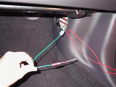
8. I tied the two greens together and connected them to the adapter
I had removed from one of the red wires and inserted this into fuse #26.
(Pic #8 also shows this. The two greens are tied together with the
white connector near the kick panel. Note the red end fom the re-used
fuse panel connector previously cut off in Step #7 (Shown in Pic #9). This
wire must be connected to a switched circuit to power down the heaters
when the car is off. Note that they will still run with the accessories
on, which could be a concern (See Addendum via BotNew56). (The connections
to fuse panel are shown in Pic #10.)
 #9
#9  #10
#10
9. The thresholds and driver kick panel can be reinstalled. The
seats are finally reinstalled, and the three plugs connected under each
seat. Finally the battery is reconnected. I did not lose anything
including radio presets. You may lose some settings such as radio,
window drop, as well as engine "learning".
10. This wiring is done with the kick panel removed, which is then replaced
after testing the heaters. (Pic #11 Shows kick panel reinstalled
with the Rostra fuses accessible.) The fuse panel cover in the kick
panel is replaced last.
 #11
#11
11. Enjoy your new bun warmers!
ADDENDUM - BotNew56 did his power connections differently which allows
power to the heaters only when the car is running. He connected to connectors
outside the fuse area, but on the same panel. Below is his description,
which I paraphrased.
The Red wire - Rather than connect to one of the fuses, I found the
wire which goes from the switch which is hot when the switch is in accessory
or run position. That can be found at pin 15 of the connector C270(a)
on the Central Junction Box (CJB) which is the circuit board that contains
the the fuses in the cockpit on the right wall of the cockpit.
The Green wires from the heaters are supposed to connect to the "ignition
on" from the ignition switch. I chose to connect to pin 4 of connector
C270(d). This is the fused side of fuse 3 in the CJB . This is hot
only when the ignition is in the "Run" position. It is off
on Accessory only, and Start positions. This way the heaters can
only be on when the engine is running.
There is a cover on the C270(a) which goes on (barely) with the connection
added.
  |